SolidWorks - Stress analysis in I-beam
Finite Element Method
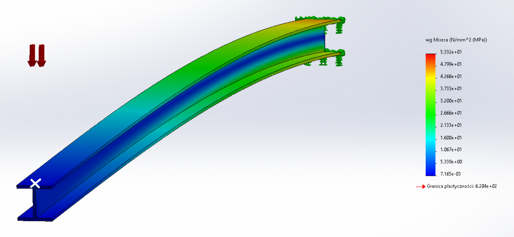
The SolidWorks software, in addition to a wide range of tools for building geometry, also provides the Simulations module that allows for thermal-structural analyzes. The example below shows a 1 m long steel I-beam. The beam is rigidly supported at one end and an external axial load is applied at the other end. The estimated maximum stress in the beam is 53.32 MPa, while its deflection is approx. 5 mm.

Suppose that exactly the same beam is loaded with the same force, but shifted from the vertical axis by 10 mm - it will be loaded eccentrically. In this case, an additional torsional effect will appear in the beam, and the maximum reduced stresses will be 62.92 MPa with a deflection of 5.4 mm.

Moved the external load by 10 mm (while maintaining all other parameters constant) resulted in an increase in stress in the beam by 18% and in deflection increase by 8%. I-beams do not cope well with the eccentric loads and require additional stiffeners to prevent warping.

